 This article describes a usage of a plotter Colorgraf 512 (HP 7475A compatible) with
OrCAD 386 for home-manufacturing printed board circuits.
This article describes a usage of a plotter Colorgraf 512 (HP 7475A compatible) with
OrCAD 386 for home-manufacturing printed board circuits.
To plot paths directly on copper from OrCAD 386 is followed by one big problem.
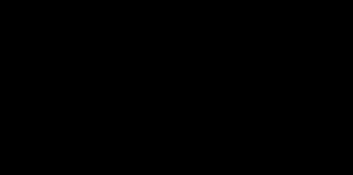
It is thanks to that the line consists of three parts. The body and two ends.
And the body pretty overlaps both ends!
The pen with special paint goes over the same place on the copper board several
times and it causes a big deposit of paint on this place. The pen is getting
dirty and track is becoming step by step less accurate. Any hole is destroyed
and lost. Some programs like EAGLE 2.62 drives plotter better and it allows
use this way without correction.
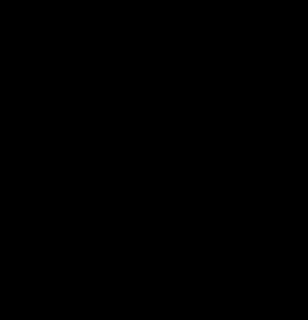
The solution is apparent. It is necessary to plot only valid parts. An output
from OrCAD is simplified by analysis and recognition of basic elements like
pads, lines and zones. Lines are cut to avoid overlaps and pads are replaced
by single circle or rectangle. And than a new nicer output file is created.
Lines from OrCAD are changed to more simple formation - single line without
end arcs. If there is a pad on the end of a line then this line is cut to not
overlap the pad. Wide line are replaced by single line too. If anybody will want to
create wide connection copper line there is a possibility to use a zone for that
purpose (as showed in zd.zip).
Pads are replaced by simple circle or rectangle.
Zones are necessary well preset in OrCAD settings to obtain zones as
a set of horizontal or vertical (not both!) lines retraced by a single line.
So no change is applied to these lines except that there is a pad inside
the zone. In that case are lines cut to not overlap the pad.
Text consists of lines so the same procedure is applied like for connection
lines.
Program, which threats HPGL output from OrCAD
386, is written in Pascal 6.0 a is considered as freeware, source code included.
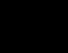
The file zd.zip contains printed board circuit for
power supply of CB transceiver Elix Giant after
correction.
Any questions are welcomed. If anyone will improve the program I would like to
obtain a copy.
Unfortunately there is no possibility to threat an output from Win95 version
of OrCAD due to a difference between HPGL instruction separator in this output.
It's, of course, my mistake... I'm sorry.
| Format | File | Size | Content |
|---|---|---|---|
| Turbo Pascal 6.0 | cudirect.zip | 15 kB | Program CuDirect.exe with source code |
| HPGL | zd.zip | 6 kB | Example of output of program CuDirect - pcb of 13.8V power supply |
 Plotting procedure is following. At first I put a new sheet of paper
to plotter and I let plot it at first right down on paper just for a test
and just to know a place where I should attach copper board by adhesive tape.
Then I adjust pen position screw to the highest position of pen above the board.
Plotting procedure is following. At first I put a new sheet of paper
to plotter and I let plot it at first right down on paper just for a test
and just to know a place where I should attach copper board by adhesive tape.
Then I adjust pen position screw to the highest position of pen above the board.
Used paint is special one just for this purpose. In Czech Republic in
Prague is possible to buy it in every shop with electronics components.
This paint is water-adulterateble so it is possible to clean the deposit pen
very easy. The type of pen is for technical tracing and its size is 0.7mm.
Etching is in combination of two parts of 5% dilution of
H2O3 (in Czech we buy peroxide in
any pharmacy or drugstore)
and one part of 33% HCL acid (in Czech we buy it in drugstore). You must mix
it carefully! Cast acid step by step slowly to dilution of
H2O3. Never in reverse order!
It goes very quickly - one two minutes and all is done.
I have got a software for ZX Spectrum +2A and HP compatible plotter too. It is possible to create double side boards of size 150x110mm.
|
|
|